
Page 187 - CW E-Magazine (8-10-2024)
P. 187
Special Report
of cycles before failure as a result of Figure-16 shows a section of a the keyway root radii and shoulder radii
which fatigue will occur. multi-stage pump shaft embedded in the at changes in section will also serve to
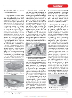
hub of a fl exible coupling. The pump decrease the stress concentration fac-
Figure-14 shows a fatigue fracture was used in a mine dewatering applica- tors at these sites. Elimination of key-
on a multi-stage pump used to pump tion and failed after approximately 600 ways would be the ideal solution, but
mine water with a pH of 7.5. In this hours in service. Failure occurred at the this is not always possible. Fatigue
case a crack initiated at the keyway root face of the coupling between the pump life can also be improved by selecting
radius and propagated approximately shaft and the motor shaft. Multiple fati- materials with higher fatigue limits.
midway through the section before fi - gue crack planes are visible (arrowed)
nal fast fracture occurred. The large fast indicating rotating bending fatigue Sleeves protect the shaft against
fracture zone (labelled ‘f’) indicates with multiple crack initiation sites. corrosion, erosion and wear and are
that the shaft was under a high nomi- The teeth of the fl exible coupling hub mainly found on large hydraulic pumps
nal stress. The pump reportedly had a showed signifi cant eccentric wear indi- (8). However, inadequate sealing of
service life of more than 3,000 hours cating angular misalignment between the sleeves will allow ingress of water,
before failure occurred. The stress con- the pump shaft and the motor shaft at resulting in under-sleeve corrosion of
centration created by the keyway root the fl exible coupling. It was concluded both sleeve and shaft as mentioned pre-
radii was probably exaggerated by the that fatigue cracks initiated at the key- viously. Common materials for sleeves
presence of corrosion pits noticed in way root and at various points along are cast-iron or bronze. If exposed to
the keyway. It is predicted(6) that the the shaft circumference and propagated water, grey CIs are likely to corrode
stress concentration factor associated under a cyclic bending stress occurring fairly rapidly. Liquid ingress under a
with a pit is 2. As stress concentrations as a result of misalignment. poorly machined or installed sleeve or
are cumulative, pits occurring on key- shaft will result in a loose fi t between
way radii will increase the effective sleeve and shaft, with the result that the
stress concentration. An illustration of components will wear against each other.
the effect of pitting is given in the photo- One such example is illustrated in Fig-
graph in Figure-15, which portrays a ure-17 and shows two sleeves from
fatigue crack growing from a corrosion a horizontal split-casing pump. The
pit observed on another pump shaft. sleeve on the left shows severe corro-
This particular pump was used to pump sion and wear when compared with the
river water and suffered numerous fati- sleeve on the right. Both sleeves are lo-
gue failures initiated by corrosion pits. Fig. 16: Fatigue failure with multiple initiation cated on opposite sides of the impeller
(arrows point to fatigue crack planes) shaft and were manufactured from CI.
Bearing failures due to ingress of It is suspected that corrosion occurred
water or dirt are common and will result due to water ingress under the sleeve,
in severe shaft vibration if not main- possibly as a result of the sleeve being
tained. High levels of vibration can slightly loose to start with. The sleeve
exaggerate fatigue and vibration should corroded to the extent that it was loose
be monitored regularly. Misalignment on the shaft, resulting in eccentric wear
of shafts occurs primarily during the and subsequent thinning of the sleeve
installation process and can be avoided walls. This type of failure can be pre-
Fig. 14: Fatigue failure initiating at a key way if the correct procedures are followed. vented by sealing the shaft by means
root radius By preventing corrosion of the shaft,
the stress concentration factor associ-
ated with pitting can be eliminated.
Corrosion on shafts can be prevented
by either sealing the shaft by means of
O-rings on the sleeves or by selecting
high alloy steels, such as SS, depending
on the application. Galvanic corrosion
can be prevented by selecting similar
Fig. 15: Fatigue failure initiating at a Fig. 17: Cast-iron sleeves showing severe
corrosion pit shaft and sleeve materials. Increasing corrosion & wear (left hand side)
Chemical Weekly October 8, 2024 187
Contents Index to Advertisers Index to Products Advertised