
Page 186 - CW E-Magazine (8-10-2024)
P. 186
Special Report
sleeve has been removed revealing All metals have a corrosion po- a crack initiation site in the form of a
severe pitting in the area directly under tential when immersed in a corrosive stress concentration. Thus, rotating ele-
the sleeve. The solution being pumped electrolyte. Thus, when two dissimilar ments on pumps, such as the shaft, are
in this case was river water, a general metals are in contact with one another susceptible to fatigue by the nature of
composition of which is presented in in a solution, a galvanic potential is their operation. Should the shaft be
Table-2. As can be seen from this table, set up between the two and may result slightly misaligned or become slightly
the water had a relatively neutral pH in preferential corrosion of the more misaligned due to incorrect installation
of 7.21. The severity of the attack in active metal. The galvanic series gives or worn bearings, a bending moment is
this case thus suggests that pitting may an indication of the potentials between created in the shaft leading to fatigue
have been assisted by a galvanic effect various metals when immersed in sea- failure.
between the steel shaft and the bronze water. The further apart the metals in
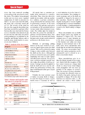
sleeves. From this water analysis it can the table, the greater the potential for Stress concentration sites on shafts
be seen that the water does not exhibit galvanic corrosion between them. Thus where fatigue cracks may initiate are
scaling tendencies, as predicted by the it can be seen that the steel shaft, being illustrated in Figure-13(5). The most
Langelier and Ryznar indexes, and as the more active metal, would corrode in common areas of crack initiation are
such the water would tend to be corro- preference to the bronze sleeve. at the stress concentrations occurring
sive to steel (Table-3). at the keyway root radius and sharp
Methods of preventing pitting changes in cross-sectional area of the
Table 2: Analysis of the river water failures of this type would be to pre- shaft. These stress concentration sites
Property Value vent any liquid ingress under the shaft should thus be avoided when designing
Total dissolved solids 180 sleeves. This can be achieved by using shafts. The stress concentration asso-
Total hardness (CaCO ) 90
3 O-ring or other suitable seals between ciated with various geometries can be
Calcium hardness 70 the shaft and the sleeve. Although lap calculated(6) and is referred to as a
Magnesium hardness 20 joints are commonly used, poor quality stress concentration factor.
Total alkalinity 80 machining will result in water ingress
Chloride as NaCl 45 and subsequent corrosion. The use of a Stress concentrations serve to re-
pH 7.21 more corrosion-resistant material may duce the fatigue strength of the compo-
Soluble iron 0.03 also reduce the problem of pitting cor- nent. Steels (with the exception of SS)
Appearance of sample Clear rosion. Coatings can also be applied to have what is known as a fatigue limit
Appearance of sediment Brown both the shaft and sleeve, but the suit- which is a stress below which fatigue
crack propagation will not occur re-
ability and performance of these coat-
Ryznar index (RSI) (20 C) 9.12 ings would depend on the type of liquid gardless of the number of cycles(7).
0
Langelier index (LSI) (20 C) -0.96 being pumped. Thus, the presence of stress concentra-
0
Ryznar index (70 C) 7.64 tors decreases the allowable stress on
0
Langelier index (70 C) -0.22 Probably the most common cause the shaft at that point, making it more
0
Concentrations in mg/l unless otherwise stated of failure on pump shafts is fatigue. susceptible to fatigue. SS on the other
In order for fatigue to occur, a cyclic hand have an endurance limit, i.e., the
Table 3: Ryznar and Langelier stabi- tensile stress is necessary as well as material can endure a finite number
lity indexes to predict the corrosive
nature of water
LSI RSI Tendency of water
2.0 <4 Heavy scale forming;
non-aggressive
0.5 5-6 Slightly scale forming;
mildly aggressive
0 6-6.5 Balanced or at CaCO
3
saturation
-0.5 6.5-7 Non-scaling and slightly
aggressive
-2.0 >8 Under-saturated and very
aggressive Fig. 13: Typical stress concentration sites on shafts
186 Chemical Weekly October 8, 2024
Contents Index to Advertisers Index to Products Advertised