
Page 184 - CW E-Magazine (3-12-2024)
P. 184
Special Report
Fig. 5: Pin holes initiated in the anode leading
to leakage of chlorine.
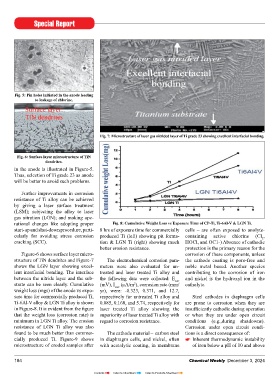
Fig. 7: Microstructure of laser gas nitrided layer of Ti grade 23 showing excellent interfacial bonding.
Fig. 6: Surface layer microstructure of TiN
dendrites.
in the anode is illustrated in Figure-5.
Thus, selection of Ti grade 23 as anode
will be better to avoid such problems.
Further improvements in corrosion
resistance of Ti alloy can be achieved
by giving a laser surface treatment
(LSM); subjecting the alloy to laser
gas nitration (LGN); and making ope-
rational changes like adopting proper Fig. 8: Cumulative Weight Loss vs Exposure Time of CP-Ti, Ti-6Al-V & LGN Ti.
start-up and shut-down procedure, parti- 8 hrs of exposure time for commercially cells – are often exposed to anolyte-
cularly for avoiding stress corrosion produced Ti (left) showing pit forma- containing active chlorine (Cl ,
2
cracking (SCC). tion & LGN Ti (right) showing much HOCl, and OC1-) Absence of cathodic
better erosion resistance. protection is the primary reason for the
Figure-6 shows surface layer micro- corrosion of these components, unless
structure of TiN dendrites and Figure-7 The electrochemical corrosion para- the cathode coating is pore-free and
shows the LGN layer showing excel- meters were also evaluated for un- noble metal based. Another species
lent interfacial bonding. The interface treated and laser treated Ti alloy and contributing to the corrosion of iron
between the nitride layer and the sub- the following data were collected: E corr and nickel is the hydroxyl ion in the
strate can be seen clearly. Cumulative (mV), I (μA/m ), corrosion rate (mm/ catholyte.
2
corr
weight loss (mgs) of the anode vs expo- yr), were: -0.323, 0.371, and 12.7,
sure time for commercially produced Ti, respectively for untreated Ti alloy and Steel cathodes in diaphragm cells
Ti-6Al-V alloy & LGN Ti alloy is shown 0.085, 0.168, and 5.74, respectively for are prone to corrosion when they are
in Figure-8. It is evident from the figure laser treated Ti alloy showing the insufficiently cathodic during operation
that the weight loss (corrosion rate) is superiority of laser treated Ti alloy with or when they are under open circuit
minimum in LGN Ti alloy. The erosion regard to corrosion resistance. conditions (e.g.,during shutdowns).
resistance of LGN Ti alloy was also Corrosion under open circuit condi-
found to be much better than commer- The cathode material – carbon steel tions is a direct consequence of:
cially produced Ti. Figure-9 shows in diaphragm cells, and nickel, often Inherent thermodynamic instability
microstructure of eroded samples after with acatalytic coating, in membrane of iron below a pH of 10 and above
184 Chemical Weekly December 3, 2024
Contents Index to Advertisers Index to Products Advertised