
Page 210 - CW E-Magazine (26-9-2023)
P. 210
Special Report
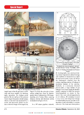
Example of Transducers Distribution on
Vessel’s Surface (1)
Typical Results Representation of Acoustic
Emission Testing (1)
1) Nondestructive Testing Handbook, volume 6
“Acoustic Emission Testing”, Third Edition, ASNT.
Fig. 16: AE testing of Hemispherical Pressure
Vessels
IR thermography was employed dur-
ing annual inspection to detect leakage
and condition of insulation in a super
thermal power plant. Figure-20 shows
the thermogram obtained from the
scanner depicting patches of leakage &
insulation damage of the pipeline.
Similarly, in a continuous chemical
process plant, a large number of gas
Fig. 15: AE Inspection of Pressure Vessels leakages were found during IR thermo-
length band of the IR spectrum is suffi- Figure-18 shows the principle of mea- graphy scanning in different pressure
cient and most suitable for thermog- suring radiant heat stress by thermo- vessels/pipelines as shown in Fig-
raphy inspection. The leakage point/ graphy. Basic Configuration of IR Imager ure-21. In a very critical inspection in
patch of the hot surface of the pressure depicting set of lenses, filters, scanning an oil refinery, IR scanning revealed
vessel (target) transmits radiant energy, element, detector and electronic system a very severe and dangerous leakage
which is detected and measured by a is illustrated in Figure-19(16). of inflammable process gas due to lin-
sensor and processed further to pro- ing defect in the oil refinery’s catalytic
duce a thermal image of the target area. In a HP steam pipeline network, converter. The black and white picture
210 Chemical Weekly September 26, 2023
Contents Index to Advertisers Index to Products Advertised