
Page 180 - CW E-Magazine (4-3-2025)
P. 180
Special Report Special Report
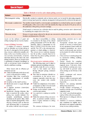
Table 1: Methods to test for and evaluate pitting corrosion 11. Use materials known not to pit in the moisture and oxygen, tin will naturally can occur at the interface without any
Method Description environment under consideration. form a protective oxide layer that is very resistance from the protective fi lm and
For example, the addition of 2% hard and brittle. When contact is initially increase the amount of friable (easily
Electromagnetic testing Electrically conductive materials such as ferrous metals can be tested for pits using magnetic molybdenum to 18-8 SS (type 304) made, the tin oxide layer will crack un- crumbled) oxide particles.
particle testing based upon the variations in magnetic fi elds generated by defects in the material. to produce 18-8 SS Mo (type 316) der the applied loading due to its brittle
Microscopic examinations The number of pits found by a microscopic examination in a defi ned surface area is counted. results in very large increase in resis- nature, exposing the fresh underlying tin. For steel alloys such as used in a
Metallography of the cross-section will help identify the shape and depth of the pit as well as tance to pitting. Under the applied load, the underlying bearing, joint or spring applications,
the acuteness of the pitting corrosion damage. tin will force its way through the cracks fretting corrosion can be easily recog-
How to fi x pitted surfaces in the tin-oxide layer to make contact at nized by the formation of hematite bet-
Weight loss test Metal sample is immersed in a chloride solution and the pitting corrosion rate is determined Corroded surfaces and pits should be the surface, resulting in a stable electri- ween the contacting surfaces. Accumu-
by examining the sample after a few days. thoroughly cleaned to render the surface cal connection. Should the contact in- lation of debris particles between the
free from corrosion debris. Pits may be terface move, the new surface layer will contacts is typical of fretting corrosion
Ultrasonic testing Echoes of sound energy refl ected by the pits are converted to electric pulses, which reveal the cleaned with the help of wire brushes become exposed to the atmosphere and as opposed to sliding wear corrosion.
location and dimensions of the pits.
and pointed tools. After inspecting the quickly form another tin-oxide layer.
occurs on the surfaces of gears and An alloy’s susceptibility to pitting mizing pitting corrosion can be sum- surface for cleanliness, a primer appli- Meanwhile, at the new contact location, The topography and the chemical
rolling bearings that are heavily loaded. is evaluated on the basis of the critical marized below(6, 7): cation can be planned and completed. A the tin-oxide layer cracks to expose the composition of the contacting surfaces
pitting temperature (CPT) for the alloy 1. Incorporate welded butt joints top coating may be applied subsequently. underlying tin to make another stable also play a critical role. This can include
Causes of Pitting Corrosion material, which is determined on the instead of riveted or bolted joints Primers based on zinc phosphate are the connection. This cycle repeats each time the initial surface roughness, formation
A solution of corrosive chemicals basis of ASTM G 48-03 for alloy steels in new equipment. Sound welds and fi rst choice for protecting metals from there is movement in the contact loca- of plastically deformed surface layers
such as chlorides can initiate pitting at and SS. The CPT is the minimum tem- complete penetration are neces- pitting corrosion. Zinc spray coating tion. Continued microscopic movement due to rubbing or impacts, relative hard-
the site of a damaged or broken passive perature at which pitting is observed. sary to avoid porosity and crevices and galvanization by hot dipping are the (fretting) will eventually result in the ness of the two surfaces, the growth and
fi lm, even on a defect-free metallic sub- The critical crevice corrosion tempera- on the inside (if welded only from other preservation techniques adopted accumulation of insulating oxide debris, the mechanical properties of oxide fi lms
strate. In the case of mildly corrosive or ture for an alloy is usually found to be one side). for preventing pitting corrosion. which can signifi cantly reduce the formed, and the formation of any reac-
non-corrosive environments, inclusions lower than the critical pitting corrosion 2. Close crevices in existing lap joints number of effective contact areas tion product layer and its adsorption.
and other defects in the metal can cause temperature (CPT). by continuous welding, caulking, What is fretting corrosion? (or asperity spots) and increase the
pitting initiation. However, in most cases or soldering. Fretting corrosion is a type of contact resistance. Microstructure of the materials and
a combination of material (metallurgy) as How to prevent or minimize pitting 3. Design vessels for complete motion-induced corrosion that results in the presence of defects can impact the
well as environment factors (chemicals) The following steps can be taken to drainage; avoid sharp corners and a build-up of oxidized wear and debris Increased contact resistance due to tribological properties and corrosion
directly contributes to pitting. minimize and prevent pitting corrosion: stagnant areas. Com plete drain- when metallic surfaces in contact with corrosion build-up can lead to poor per- resistance of the surfaces. These can
Carefully study the service environ- ing facilitates washing and clean- each other are subjected to small (in the formance and failure in a variety of elec- include phase distribution, non-metallic
Other factors able to infl uence pit ment so that metals and alloys ing and tends to prevent solids order of a few tens of microns) repetitive trical devices. In low current circuits, inclusions, segregations and grain size
formation include: having adequate pitting resistance from settling on the bottom of the motions. These microscopic movements increased resistance can cause frequent and orientation. For example, the pre-
A lack of uniformity in thickness and are chosen. vessel. can occur because of vibration, thermal drops and even interrupt the electrical sence and thickness of the oxide fi lm can
cracks in the protective coating; Take steps to minimize chloride ion 4. Inspect equipment and remove expansion/contraction or mechanical signals. However, in high current cir- impact the level of plastic deformation
Turbulent fl uid fl ow occasionally concentration in the service envi- deposits frequently. and thermal shock(3, 8). cuits, these small increases can result and depth of surface penetration made
causing impingement of metallic ronment, especially where they may 5. Remove solids in suspension early in overheating, which can eventually by the harder asperities into the softer
surfaces; come into contact with metallic in the process or plant fl ow sheet, Fretting corrosion is not a newly lead to device failure. surface.
Scratches on the metal’s surface; surfaces. if possible. discovered failure mode. It was initially
Insuffi cient access to oxygen (through Control the temperature of the indoor 6. Remove wet packing materials described in 1911 by Eden, Rose and Oxidation is the most common cor- Examples of fretting corrosion
aeration); environment so that it does not reach during long shutdowns. Cunningham in reference to a type rosive environment for fretting corro- The surgical alloys that have been
A stagnant moisture (electrolyte) the CPT level for the material. 7. Provide uniform environment, if of corrosion observed on a steel part sion. As fi ne, deformed metal particles used in modular hip implants owe their
condition; and Design anodic/cathodic systems for possible, as in the case of backfi lling of a fatigue testing machine. In 1939, are removed from a surface by the corrosion resistance to the formation of
Insuffi cient alloying elements that corrosion prevention. a pipeline trench. Tomlinson, Thorpe and Gough termed mechanical cyclic motion, they are a stable passive oxide fi lm. However, the
help re-passivate the surface where Use a protective coating on metallic 8. Use ‘solid’, non-absorbent gaskets, the phenomenon “fretting corrosion”. oxidized and trapped between the fretting repetitive motion at the ball and socket
pitting was recently initiated. For surfaces. such as Tefl on wherever possible. Since then, fretting corrosion has been surfaces. These oxide particles then act of the hip replacement implant can lead
example, molybdenum enriches Polish the surfaces if they are acces- 9. Weld instead of rolling in tubes in observed on soft metals such as aluminium as an abrasive with a subsequent increase to fretting corrosion with a continuous
chromium in the passive fi lm, which sible, as polished metallic surfaces tube sheets. and on hardened steels. in material removal. If the damaged breakdown and re-passivation of the
helps to heal the damaged fi lm. Other have a higher resistance to pitting 10. Addition of corrosion inhibitors passive fi lm cannot be re-passivated, protective oxide layer. Continued
alloying elements such as titanium corrosion(4, 5). may sometimes be helpful, but if Let us consider, for illustration pur- further material loss will occur. In repeated breakdown and re-passivation
and chromium help to re-passivate the attack is not stopped completely, poses, two tin-plated electrical connec- addition, when the surface passive fi lm is consumes the oxygen in the removed
the surface with the help of oxygen. The common techniques for mini- it may increase pitting tendency. tors in direct contact. When exposed to mechanically damaged, charge transfer metal, which can then promote the
180 Chemical Weekly March 4, 2025 Chemical Weekly March 4, 2025 181
Contents Index to Advertisers Index to Products Advertised