Page 182 - CW E-Magazine (2-7-2024)
P. 182

Special Report


                                                                          specimen. The time taken for the sound
                                                                          to traverse the thickness of a specimen
       Receive socket         Transmit socket
                                                                          and return to the probe is usually dis-
           LCD
                                                                          played on an oscilloscope and refl ects
                                                                          the distance the pulse has travelled and
                                                                          thereby the thickness of the specimen.
           Case
                                                                          This technique is widely used for crack
                                                                          detection and  thickness  monitoring of
          Keypad                Transducer                                in-service equipment that may suffer
                                                                          from erosion-corrosion. Figure-16-A
                                                                          shows the oscilloscope screen depict-
         Sample block                                                     ing initial pulse, echo from the back
                            Battery compartment
                            (rear case)                                   side of the specimen, and the echo from
                                                                          the corrosion pit, using a normal probe.
        Fig. 17: Direct reading ultrasonic thickness   Fig. 18: Inspection Grid For UT Measurement   Figure-16-B shows oscilloscope screen
                  gauge/meter                       In Pipe  Bend
                                                                          depicting echo from an internal crack in
                                                                          the specimen, using an angle probe.

                                                                             For monitoring thickness reduction
                                                                          of equipment wall due to uniform
                                                                          corrosion or erosion corrosion, an instru-
                                                                          ment called ‘Direct reading ultrasonic
                                                                          thickness meter’ is used (Figure-17).

                                                                             Figure-18 shows an inspection grid
                                                                          for thickness data  recording  for pipe
                                                                          bend showing weld joints and data col-
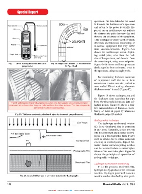
          The D-Meter probe transmits ultrasonic pulses into the sample being measured and
        receives their echoes after they are refl ected from the other surface. The time elapsed is   lection points. Figure-19 shows a real-
                           converted into thickness readings.             life demonstration  of  thickness moni-
                                                                          toring of tubes & pipes by ultrasonic
             Fig. 19: Thickness monitoring of tubes & pipes by ultrasonic gauge (D-meter)  thickness gauge (D-meter).
                                                                          Radiographic technique
                                                             X or Y-rays     This technique can be used to iden-
                                                                          tify  fl aws  developed  due  to  corrosion
                                                                          in any asset. Generally, x-rays are sent
                                                                          into the component and a picture is deve-
          Not detectable crack
                                     Detectable crack                     loped on a photographic film. Flaws
                                                                          such as cracks due to stress corrosion
                      Pit                                   Test Specimen  cracking in welded joints, deposit for-
                                                                          mation and/or corrosion pitting in tubes
                                                                          can be located before a catastrophic
                                                          Photographic Film  failure of the asset takes place. Figure-20
                                                                          shows the principle of operation of
                                                                          radiographic technique.

                                                            Developed Film
                                                                          Hydrogen penetration monitoring
                                                                             In acidic process environments,
                                                                          hydrogen is a by-product of the corrosion
                                                                          reaction. Hydrogen generated in such a
                 Fig. 20: Crack/Pit/Flaw due to corrosion detection by Radiography  reaction can be absorbed by steel parti-


       182                                                                       Chemical Weekly  July 2, 2024


                                      Contents    Index to Advertisers    Index to Products Advertised
   177   178   179   180   181   182   183   184   185   186   187