
Page 181 - CW E-Magazine (2-7-2024)
P. 181
Special Report Special Report
niques are used in an increasing range technique is that, if a corrosion upset working on the principle of ER mea- ER probes are available in a variety Galvanic Monitoring (SRB). This is a class of anaerobic bac-
of applications because: occurs during the period of exposure, surement is shown in Figure-11. of element geometries, metallurgies The galvanic monitoring technique, teria which consume sulphate from the
They are easy to understand and the coupon alone will not be able to and sensitivities and can be confi gured also known as Zero Resistance Amme- process stream and generate sulphuric
implement; identify the time of occurrence of the ER probes can be thought of as for fl ush mounting such that pigging try (ZRA) is another electrochemical acid, a corrosive which attacks produc-
Equipment reliability has been upset and depending upon the peak “electronic” corrosion coupons. Like operations can take place without the measuring technique. In this, two elec- tion plant materials. A probe for SRB is
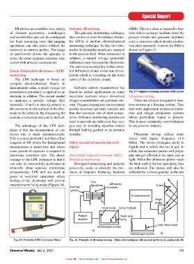
demonstrated over many years of value of the upset and its duration, may coupons, ER probes provide a basic necessity to remove probes. The range trodes of dissimilar metals are exposed shown in Figure-15.
operational application; not even register a statistically signifi - measurement of metal loss, but unlike of sensitivities allows the operator to to the process fl uid. When immersed in
Results are easy to interpret; cant increased weight loss. coupons, the value of metal loss can be select the most dynamic response con- solution, a natural voltage (potential)
Measuring equipment can be made measured at any time, as frequently as sistent with process requirements. difference exits between the electrodes.
intrinsically safe for hazardous area Therefore, coupon monitoring is required, while the probe is in-situ and The current generated due to this poten-
operation; and most useful in environments where cor- permanently exposed to the process Linear Polarization Resistance (LPR) tial difference relates to the rate of cor-
Users have experienced signifi cant rosion rates do not signifi cantly change stream. Figure-12 depicts standard ER monitoring rosion which is occurring on the more
economic benefi t through reduced over long time periods. The LPR technique is based on active of the electrode couple.
plant down time and plant life complex electrochemical theory. In
extension. Corrosion rate = KW/DAT fundamental terms, a small voltage (or Galvanic current measurement has
K = 534 (constant); W = Weight polarization potential) is applied to an found its widest applications in water Fig. 15: Sulphate reducing bacteria (SRB) probe
Corrosion coupons (weight loss) Loss (mg); D=Density of Specimen (g/ electrode in solution. The current needed injection systems where dissolved Ultrasonic testing
The Weight Loss technique is the cc); A = Area of Specimen (sq.in) to maintain a specifi c voltage shift oxygen concentrations are a primary con- These are devices designed to mea-
best known and simplest of all corrosion T = Exposure Time (hr). (typically 10 mV) is directly related to cern. Oxygen leaking into such systems sure erosion in a fl owing system. They
monitoring techniques. The method in- the corrosion on the surface of the elec- greatly increases galvanic currents and fi nd wide application in process indus-
volves exposing a specimen of material Electrical Resistance (ER) Monitoring trode in the solution. By measuring the thus the corrosion rate of steel compo- tries and oil/gas production systems
(the coupon) to a process environment The ER technique measures the current, a corrosion rate can be derived. nents. Galvanic monitoring systems are where particulate matter is present.
for a given duration, then removing the change in Ohmic resistance of a cor- used to provide an indication that oxy- This is most commonly used technique
specimen for analysis. The weight over roding metal element exposed to the Fig. 12: Standard ER probe (wire loop The advantage of the LPR tech- gen may be invading injection waters in any process industry.
the period of exposure is expressed as process stream. The action of corrosion elements) showing different degrees of nique is that the measurement of cor- through leaking gaskets or de-aeration
corrosion rate. In a typical monitoring on the surface of the element produces metal loss – insignifi cant loss (top), 50% loss rosion rate is made instantaneously. systems. Ultrasonic testing utilizes sonic
(middle), & about 100% loss (bottom)
program, coupons are exposed for 90- a decrease in its cross-sectional area This is a more powerful tool than either waves with higher frequency (1-6
day duration before being removed for with a corresponding increase in its coupons or ER where the fundamental Other specialized monitoring tech- MHz). The waves propagate easily in
a laboratory analysis (Figure-10). electrical resistance. The increase in 100 measurement is metal loss and where niques liquids and in solids, but not in gas. In
resistance can be related directly to metal 5 12 some period of exposure is required to solids, the ultrasonic pulses will propa-
loss and the metal loss as a function of 75 MPY MPY determine corrosion rate. The disad- Microbially induced corrosion (MIC)/ gate and get refl ected in the same way as
25
time is by defi nition the corrosion rate. E/R Monitor Reading 50 MPY vantage to the LPR technique is that it Biological monitoring light. When the ultrasonic pulses reach
Although still a time averaged tech- can only be successfully performed in Biological monitoring and analysis the back wall of the test specimen, they
nique, the response time for ER moni- 25 relatively clean aqueous electrolytic generally seeks to identify the pre- are refl ected. The pulses will also be
toring is far shorter than that for weight 0 2 4 6 8 10 12 14 environments. LPR will not work in sence of Sulphate Reducing Bacteria refl ected by in-homogeneity in the test
loss coupons. A typical Corrosometer gases or water/oil emulsions where
Time (Days)
fouling of the electrodes will prevent Test
Fig. 13: Graph showing ER probe reading vs measurements being made (Figure-14). Specimen Ultrasonic Crack
time in days indicating corrosion rates Normal pulses
probe
Fig. 10: Corrosion Coupons Fabricated From probe (wire loop elements) indicating
Commercially Available Alloys insignifi cant, 50%, and about 100% Pulser/receiver
The simplicity of the measurement metal loss shown as top, middle, and Angle
probe
is such that the technique forms the bottom of the figure respectively. Initial pulse Echo from pit
baseline method of measurement in Figure-13 indicates different corrosion
many corrosion monitoring programs. rates with respect to usage response Pulser/ Back side
The technique is extremely versatile, times. receiver echo
since weight loss coupons can be fabri- Echo from crack
cated from any commercially available ER probes have all the advantages Ocilloscope screen
alloy. of coupons. In addition, they respond a) Ocilloscope screen b)
Fig. 11: Electrical Resistance (Er) Monitoring quickly to corrosion upsets and can be
The disadvantage of the coupon – Corrosometer used to trigger an alarm. Fig. 14: Portable LPR Corrosion Meter Fig. 16: Principle of ultrasonic testing – Pulse echo technique with normal probe (a) & angle probe (b)
180 Chemical Weekly July 2, 2024 Chemical Weekly July 2, 2024 181
Contents Index to Advertisers Index to Products Advertised