Page 176 - CW E-Magazine (7-11-2023)
P. 176

Special Report


                                                                          fouling  with operating time of the shell
                                  Flow direction                          and tube heat exchanger is  shown  in
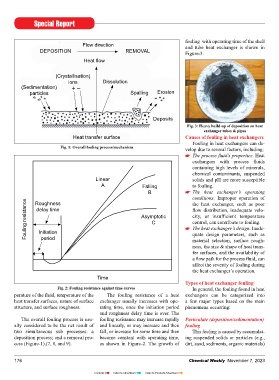
                 DEPositioN                        REmovAL                Figure-3.
                                  Heat flow


                       (Crystallisation)
                            ions          Dissolution
         (sedimentation)     + –
             particles                               spalling  Erosion


                                                              Deposits
                                                                           Fig. 3: Heavy build-up of deposition on heat
                                                                                  exchanger tubes & pipes
                              Heat transfer surface                       Causes of fouling in heat exchangers
                                                                             Fouling in heat exchangers can de-
                         Fig. 1: Overall fouling process/mechanism        velop due to several factors, including:
                                                                              The process fluid’s properties. Heat
                                                                             exchangers  with  process  fluids
                                                                             containing high levels of minerals,
                                                                             chemical  contaminants, suspended
                                       Linear                                solids and pH are more susceptible
                                         A               Falling             to fouling.
                                                            B                 The  heat  exchanger’s  operating
                                                                             conditions. Improper operation  of
           Fouling resistance  delay time                Asymptotic           The heat exchanger’s design. Inade-
               Roughness
                                                                             the  heat exchanger, such as poor
                                                                             flow  distribution,  inadequate  velo-
                                                                             city,  or  insufficient  temperature
                                                             C
                                                                             control, can contribute to fouling.
                initiation
                                                                             quate design  parameters, such  as
                 period
                                                                             material selection, surface rough-
                                                                             ness, the size & shape of heat trans-
                                                                             fer surfaces, and the availability of
                                                                             a flow path for the process fluid, can
                                                                             affect the severity of fouling during
                                                                             the heat exchanger’s operation.
                                        time
                                                                          Types of heat exchanger fouling
                        Fig. 2: Fouling resistance against time curves       In general, the fouling found in heat
       perature of the fluid, temperature of the   The fouling resistance  of a heat  exchangers  can  be  categorized  into
       heat transfer surfaces, nature of surface  exchanger usually increases with ope-  a few major types based on the main
       structure, and surface roughness.  rating time, once the initiation  period  phenomena occurring:
                                         and roughness delay time is over. The
          The overall fouling process is usu-  fouling resistance may increase rapidly  Particulate (deposition/sedimentation)
       ally considered to be the net result of  and linearly, or may increase and then  fouling
       two simultaneous sub processes: a   fall, or increase for some time and then   This fouling is caused by accumulat-
       deposition process; and a removal pro-  become constant  with  operating time,  ing suspended solids or particles (e.g.,
       cess (Figure-1).(7, 8, and 9).    as shown in Figure-2.  The growth of  dirt, sand, sediments, organic materials)


       176                                                                  Chemical Weekly  November 7, 2023


                                      Contents    Index to Advertisers    Index to Products Advertised
   171   172   173   174   175   176   177   178   179   180   181